Workflow engines like Temporal and Azure Durable Functions have emerged in recent years to simplify the complexity of building robust, long-running, and stateful applications in distributed environments. I love these technologies because workflow engines offer an effective and relatively simple solution to scalability, reliability, and maintainability, qualities traditionally difficult to achieve in distributed systems, as highlighted in the literature [5].
Developing workflow engines can sometimes feel like figuring things out as you go. You end up building based on what seems to work, addressing issues as they pop up. This can make the codebase more complicated and make it harder to build a truly robust and scalable system. Unfortunately, industrial engines rarely document their internal design and there are very few formal attempts to understand the semantics of workflow engines (notable exceptions are [6] and [7]).
In the rest of this post, we assume that a workflow is a network whose nodes are computations that we call activities. The high level architecture of a workflow engine is described in the following picture and consists of an orchestrator, a scheduler, a planner and one or more workers.
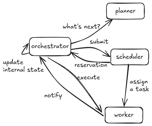
The orchestrator is the brain that coordinates several components. The planner is the component that decides which activities should be executed next, the scheduler assigns tasks (e.g. “execute activity send-email“) to workers and workers carry out the actual computation. The orchestrator updates its internal state accordingly.
A crucial component is the planner. Given a workflow and its current state, we want to know which activities should be scheduled and in which order. In addition, when an activity is completed, we want to update the state of the workflow in a proper way. In other words, the planner acts as a sort of machine that executes workflows. You may think of it also as an interpreter that processes code written in a fancy workflow-like language instead of Javascript or Python. How can we define the semantics of this machine? This is the question we are planning to answer in this blog post.
Here is how we intend to proceed. First, we briefly remind that workflows can be represented as string diagrams [2] [8]. Then, in order to build a workflow engine, the question we want to investigate is how we can “execute” a string diagram that represents a workflow. In theory, we could think of building some sort of functor to map a string diagram to something executable like a function. However, we want to run the string diagram in a distributed manner like outlined in the abstract architecture above. In order to do this, we define an abstract machine à la Krivine following the Relational Machine from [1]. The fundamental idea is that the abstract machine “outputs” tasks that will be executed by a pool of workers, concurrently. Here, it is crucial that tasks for the same workflow are independent in such a way that they can be executed in parallel.
The Abstract Machine
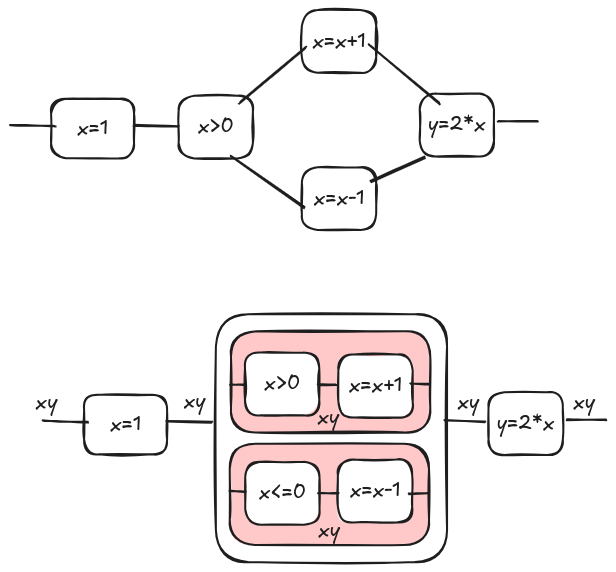
Let’s consider the following workflow on the top. It can be represented as the tape diagram [2] on the bottom. From now on we will consider only tape diagrams instead of workflows. Please read our other blog posts and cited literature for more (here, here, and here). Note that, since a tape diagram can be a representation also for an imperative programs, the machine can run both workflows and programs. Workflow and programs act as ‘user interfaces’; some users might prefer workflows due to the reduced amount of code, while more experienced users might opt for writing code directly. However, this choice does not alter the underlying execution semantics.
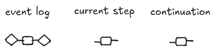
Following [1], a state is a triple of string diagrams $(E, S, C)$ that we call the event log, the current step, and the continuation, respectively.

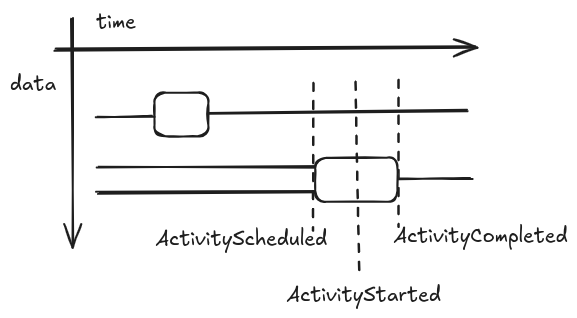
The event log represents the past history of the execution. The idea to represent runs of a process using morphisms in a symmetric monoidal category dates back to [4] where the author used them for describing executions of Petri Nets. We represent the event log as a string diagram, but, in a more familiar setting, we could think about it as a sequence of events corresponding to the syntactic elements that compose the string diagram. This correspondence is shown in the diagram below. A string diagram extends in time from left to right. The position along the time line tells which events happen before the others. Hence, from the diagram, we can recover a list of events (e.g. ActivitySchedule, ActivityStarted, and ActivityCompleted) with their data.
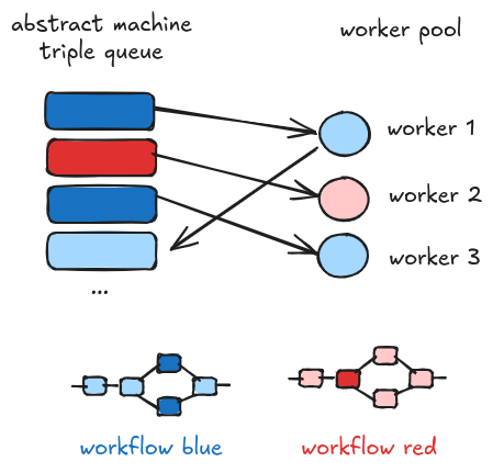
For the same workflow we can have multiple triples at a given time. The reason is that parts of a workflow can be executed in parallel and each triple is processed by a different worker. In the following picture, we show the ideal architecture where triples are stacked to a queue that is consumed by multiple workers. The dark shades indicates the current steps of workflows that are being processed in parallel. Here, two workers are processing two distinct steps of the blue workflow, while only one worker is processing a step of the red workflow. Once a triple is processed, a new one is enqueued. Please note that the queue is an implementation detail; in some situations we prefer other data structures in particular when a FIFO policy is not desirable.
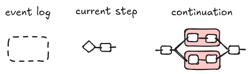
The initial state for a workflow $w$ is a triple $(s, \epsilon, w)$ where $w$ is the string diagram representing the workflow, $\epsilon$ is the empty diagram and $s$ is the input. We represent the input $s$ as a diagram with no input as seen in [3]. In the following picture, we illustrate an example of initial state. This configuration corresponds to the event WorkflowStarted in Azure, in the sense that the workflow has started and the initial triple is ready to be processed by a worker.
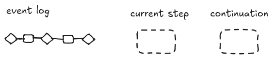
As we have an initial state, we might have a final state if the workflow terminates. We denote a final step with the following triple. Intuitively, a state is final if the current step and the continuation are the empty diagram, i.e. nothing else is left to be processed. The event log is a linear diagram representing the steps that led us to the final one. We will come back to it later to explain the graphical notation. In Azure, the final state corresponds to the event WorkflowCompleted.
A workflow run is a sequence of steps from the initial step to maybe the final step. The semantics can be defined formally. Here, we provide an example of a run, but we follow the operational semantics defined in [1]. Note that, in the original paper, continuations are Kleene algebra terms, which are basically string diagrams [2].
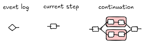
From the initial state, we can move to a state where we schedule one or more activities, i.e. ActivityScheduled event in Azure. The current step is the next activity that is popped out from the workflow.
If the state has an activity scheduled, it waits for a worker to become available. When a worker is ready, the state is changed to ActivityStarted and, graphically, it is represented as follows. Intuitively, we “run” the step with the latest known state of the workflow. In practice, some information about the assigned worker is attached to the current step, but it is not shown here because it is an implementation detail.
Once the worker terminates, the activity is marked as completed. We denote an activity as completed composing the step with a diagram with no output, [3] call these diagrams events or co-states because they are the mirrored version of a state. Here, to avoid confusion with events of the event log, we will stick to the term co-state; an event log event is more a pair step and co-state. Finally, we push back the step and co-state to the event log.
Here, we pause a second to discuss again the event log. In general, a string diagram does not represent a function. For example, [2] and [8] use relations to define the semantics of flowcharts and programs. However, the event log must be functional. The reason is that every time we replay the event log we want to get the same result. For this reason, we cannot push to the event log a copy of the continuation diagram, but we have to add co-states like a sort of checkpoints that witness the data actually observed on the wires after an activity is completed. If you are familiar with Event Sourcing, co-states stand to snapshots of the event log.
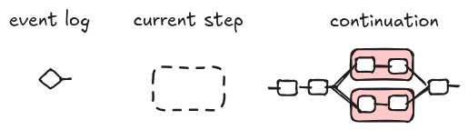
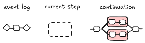
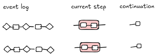
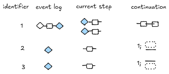
From one state, more states can be generated. State triples are processed independently by multiple workers without the risk of race conditions. This is the case of tape diagrams (red boxes) that represent alternative flows. For example, after a few steps, we end up in a situation where on the queue we have two triples for the same workflow corresponding to alternative choices (the semantics is the same as the semantics for choice in [1]). The workflow engine can work non-deterministically! This is an interesting feature when we want to explore all the possible alternatives. In the current example, however, only one of the two triples will lead to the final state because only one of the two steps can be reduced to a non empty diagram.
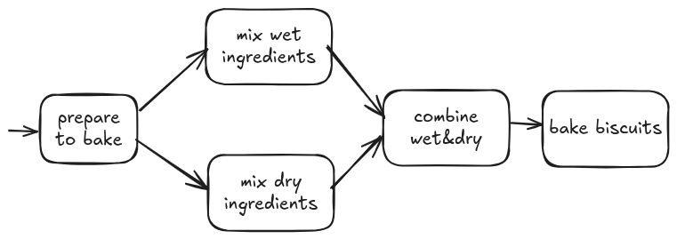
Even if we don’t want non-determinism, there is another more useful scenario when more triples for the same workflow are in the queue. Think about parallel processing: a workflow implements a fan-out pattern: some data are copied over multiple steps that run in parallel. For example, when you bake some cookies, you can mix wet and dry ingredients separately and at the same time (if you are an octopus).
It is similar to the case for non-determinism, but a bit more convuluted. We need special continuations for the parallel branches to report their results and a join mechanism to collect the results. Here, I don’t expect to give a complete and correct solution, but just a blueprint of how it is supposed to work.
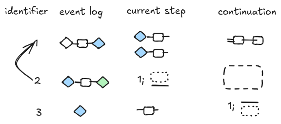
The queue for a parallel activity looks like the diagram below.
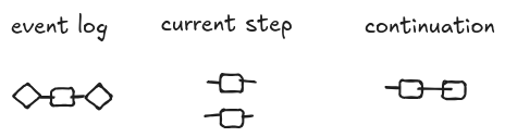
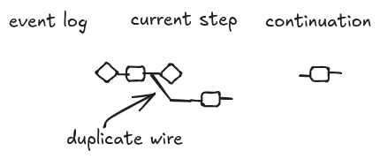
When the orchestrator processes the triple, it creates two new triples corresponding to the two branches. The initial triple current step has two states attached on the left, but it is open on the right, meaning that the execution for this step is not completed yet. Note that we can split the event log state because of our assumption that event logs are functional. The new triples have a new kind of continuation that references the parent triple and describes how the partial results should be merged back to the parent triple (more later).
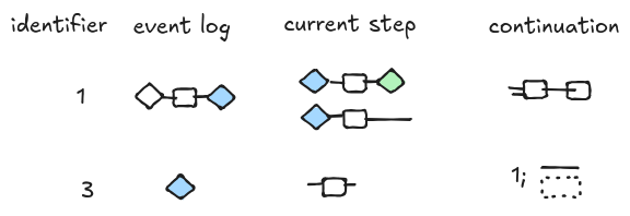
Once one of the two sub workflows is completed, the continuation is executed. The continuation contains the instructions that tell the orchestrator how to compose the event with the parent workflow.
The parent workflow’s step is updated with the information provided by the sub workflow.
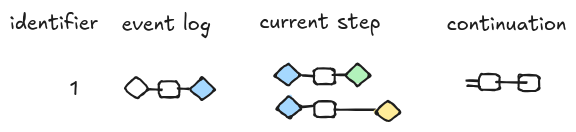
We perform similar steps for the second sub-workflow and the final result is depicted below. Now the current step is marked as completed and can be pushed back to the event log. Note that the event log contains the information about the order of execution of the two sub-workflows (e.g. “green” happened before “yellow” in this particular run).
More notes
I omitted several details above to keep it simple and help sharp our intuition. However, there is more to say.
For example, what are states and co-states in tape diagrams? They are equality predicates and their transposes.
In addition, we should be more precise and define how to “apply” an event log to a step. For example, consider the following triple. The event log does not have any output, so how can we compose it with the step?
A possibility is illustrated below (it is conditioning in [2]). The event logs above could be interpreted as syntactic sugar for this more complex diagram.
However, there might be better alternatives.
On transactions, retries, and errors
Some random notes and thoughts.
Transactions
A key point in the implementation is that state transitions must be transactional in order to avoid race conditions.
Retries
The checkpointing ensures that if the process is interrupted, the workflow can resume from the last consistent state recorded in the event log.
Determinism
The event log is deterministic by construction: if we rerun it we obtain the same result. However, the execution of the same workflow can produce different results in each workflow instance. More specifically,
- Execution of the same step on different instances gives different results. For example, let’s suppose that a step performs some API calls. API calls with the same endpoint and input may produce different output, for example, it might fail.
- Execution of parallel steps on different instances can produce different results depending on the order of execution of the steps.
Also within the same instance we have non-determinism due to the choice operator. In practice, we use choice to model conditional behavior, so only one alternative will be chased in a deterministic way. However, there are scenarios where we would like to evolve our execution over all the possible alternatives. Suppose, for example, that we want to do some Reinforcement Learning for an agent; in this case we want to explore alternatives in order to pick the configuration that yields better results for our agent.
On scalabilty and concurrency
I think the approach sketched here is different from that of other workflow engines such as Azure Durable Functions and it might overcome the scaling limitations of those technologies.
In Azure Durable Functions (and likely Temporal), workflow instances are processed by only one worker at a time to maintain state consistency. Since the workflow steps happen sequentially, one after the other, two parts of a workflow cannot change the same in-memory state at the same time. In other words, we can say that state changes are serialized within a single instance at run time, that is, when the instance is executed.
In our architecture, we also need to serialize state changes in order to avoid race conditions, but this happens at compile time when a workflow is encoded into a tape diagram. Indeed, a tape diagram makes explicit the data dependencies between parts of a workflow. Then, during the execution of the abstract machine, its semantics ensures that only independent triples are put on the queue. In other words, if two parts of the same workflow are on the triple stack at the same time, it means that they can run in parallel without side effects for the other.
In Azure, scalability is limited by the number of workers because, as we have discussed, an instance is processed by a single worker. A higher count can potentially allow for more concurrent workflow instances, but it consumes more compute resources. Unfortunately, the number of workers cannot be changed dynamically making it hard to calculate the right trade off between parallelism and resource consumption. Activities, on the other hand, can scale more elastically as they are processed from a single queue by any available worker.
In our architecture, the machine triples are processed in parallel by a pool of workers and parts of the same workflow instance can be processed by multiple workers without race conditions. So it is a model closer to how activities (and not workflows) are processed in Azure. Hence, we can scale out based on demand in theory. In practice, we may need to consider that factors of a parallel term should reasonably run in the same region because some communication is involved for parallel computations.
What do you think? Does it make sense?
Acknowledgments
I gratefully acknowledge Gemini’s helpful input. All inaccuracies, however, are the sole responsibility of… Gemini. I used AI for researching, drafting the boring parts, and spell-checking. I edited and elaborated the generated text trying not to change my “natural” style.
References
[1] Barrett, Chris, Daniel Castle, and Willem Heijltjes. “The Relational Machine Calculus.” Proceedings of the 39th Annual ACM/IEEE Symposium on Logic in Computer Science. 2024. pdf
[2] Bonchi, Filippo, Alessandro Di Giorgio, and Elena Di Lavore. “A Diagrammatic Algebra for Program Logics.” arXiv preprint arXiv:2410.03561 (2024). pdf
[3] Kissinger, Aleks, and Bob Coecke. “Picturing Quantum Processes.” (2015).
[4] Sassone, Vladimiro. “The algebraic structure of Petri nets.” Current Trends in Theoretical Computer Science: The Challenge of the New Century Vol 1: Algorithms and Complexity Vol 2: Formal Models and Semantics. 2004. 385-410. pdf
[5] Kleppmann, Martin. “Designing data-intensive applications.” O’Reilly (2019).
[6] Burckhardt, Sebastian, et al. “Durable functions: Semantics for stateful serverless.” Proceedings of the ACM on Programming Languages 5.OOPSLA (2021): 1-27. pdf
[7] Burckhardt, Sebastian, et al. “Netherite: Efficient execution of serverless workflows.” Proceedings of the VLDB Endowment 15.8 (2022): 1591-1604. pdf
[8] Stefanescu, Gheorghe. Network algebra. Springer Science & Business Media, 2000.